Wiring! Rear distribution panel done!

TinBoats.net

Help Support TinBoats.net:

This site may earn a commission from merchant affiliate links, including eBay, Amazon, and others.

T Man

Well-known member
Joined
May 24, 2010
Messages
254
Reaction score
0
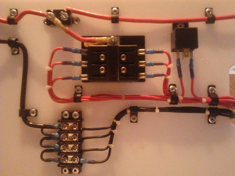
I tore my decks off, and gutted my wiring in my boat and have been fixing little things here and there, and painting the bilge area. Finally today I am seeing a little bit of forward progress. I ran out of ring connectors, but I got the rear/main distribution panel is DONE. I have 1 more smaller one to make under the console, one to make up front, and a switch panel to make, and then the wiring can be re-run and get the boat floated again!

 
That looks great!

I would like to do something like that. I don't know what most of those components in your picture are called. Could you make a list of the components in your picture, using trade names if possible, so I can research more about how to do this?
 
Nice work. Looks extremely clean!! One of the messiest parts of my boat project was wiring. Still need to tidy mine up, but am waiting until I get my motor bolted on, controls run and trolling motor installed. When does your season start? You planning on having everything ready by then?
 
Looks good, definitely needs labels and wire numbers for the fuses. If there's a chance of condensation I'd try to put weep bends in the lines so the water doesn't migrate into the fuse panel etc. Dollop some dialectic grease on the terminals before you put the ring terminals on and cover them once you are done will help prevent green death.

When I worked for Lucent Tech doing install work in phone exchanges we would sew the lines in with a waxed cord. I think 80% of the work was making everything look nice. Sewing in 500MCM to the battery banks was a hoot, 9" deep x 16" wide of 1" cables.
 
[url=https://www.tinboats.net/forum/viewtopic.php?p=329889#p329889 said:
Jeffrey » Today, 06:17[/url]"]That looks great!

I would like to do something like that. I don't know what most of those components in your picture are called. Could you make a list of the components in your picture, using trade names if possible, so I can research more about how to do this?


The relay will be for the switched bilge pump. I am also going to run relays on my lights in the front so I can run smaller gauge wire from the switch panel. This will let me use a smaller diameter conduit. There will be a switched bilge pump, automatic bilge pump, led strip, and possibly a light for the bilge run off of this fuse panel. Coming off of the main breaker will be a 10 gauge wire running to a fuse panel under the dash that will run the headlights, nav lights, fish finder, and cigarette lighter/12v outlet.

RiverBottomOutdoors said:
Nice work! I probably would have used screws instead of rivets of my cable clamps.

Its not too late to drill them out. Why screws instead of clamps? Just for the ability to remove it easily?

BigTerp said:
Nice work. Looks extremely clean!! One of the messiest parts of my boat project was wiring. Still need to tidy mine up, but am waiting until I get my motor bolted on, controls run and trolling motor installed. When does your season start? You planning on having everything ready by then?

I hope so. We have a 2 day (?) season Nov. 2 and 3, and then our season doesn't open up until Nov. 22nd.

Ranchero50 said:
Looks good, definitely needs labels and wire numbers for the fuses. If there's a chance of condensation I'd try to put weep bends in the lines so the water doesn't migrate into the fuse panel etc. Dollop some dialectic grease on the terminals before you put the ring terminals on and cover them once you are done will help prevent green death.

When I worked for Lucent Tech doing install work in phone exchanges we would sew the lines in with a waxed cord. I think 80% of the work was making everything look nice. Sewing in 500MCM to the battery banks was a hoot, 9" deep x 16" wide of 1" cables.

I have some noalox that I am going to put on all of the terminals when it comes time to install it. No reason to spend all the money on heat shrink connectors, but let the terminals corrode. I hadn't thought about about weep bends, but its not a bad idea. Ill see what I can get figured out.
 
T man looking at this I am in awe that someone would go to the great lengths you did to make it look good. I work for a high end ski boat shop and some of the wiring hacks I have seen would make people cry. On the relay though, I see the power you have for it coming from the fuse block, the other terminal you have the red wire coming to is the ground to complete the relay and make it switch. I am not aware of a bilge pump float switch that sends a ground signal to make the complete circuit, correct me if I am wrong, but I would expect the power from the fuse to go to the terminal that is sideways compared to the rest then the middle terminal to go to the float switch power, so it is hot at all times. Excuse me that I don't recall the exact terminal numbers off the top of my head.
 
[url=https://www.tinboats.net/forum/viewtopic.php?p=329933#p329933 said:
Snowman6479 » Today, 16:23[/url]"]T man looking at this I am in awe that someone would go to the great lengths you did to make it look good. I work for a high end ski boat shop and some of the wiring hacks I have seen would make people cry. On the relay though, I see the power you have for it coming from the fuse block, the other terminal you have the red wire coming to is the ground to complete the relay and make it switch. I am not aware of a bilge pump float switch that sends a ground signal to make the complete circuit, correct me if I am wrong, but I would expect the power from the fuse to go to the terminal that is sideways compared to the rest then the middle terminal to go to the float switch power, so it is hot at all times. Excuse me that I don't recall the exact terminal numbers off the top of my head.

I am going to run 2 bilge pumps. The primary will be on a float switch coming directly off the fuse block, and the aux. will be switched and on the relay.

Nice catch on the terminals. No matter how many I install, i always have to go back and figure out which posts are which. The 30 and 87 terminals are the power and the 85 and 86 are the trigger. I need to put the 2 leads on the other posts and put a ground wire on the 85 post. It should look like this:

relay-diagram.gif
 
You know what I like using, is a PT193 pre wired harness for the relays, I get them from orielly auto here in Texas. They make for am easy plug in and unplug, with one connector.
 
[url=https://www.tinboats.net/forum/viewtopic.php?p=329976#p329976 said:
Snowman6479 » Yesterday, 09:11[/url]"]You know what I like using, is a PT193 pre wired harness for the relays, I get them from orielly auto here in Texas. They make for am easy plug in and unplug, with one connector.

I like it. May have oreillys order me a few (not in stock here)
 

Latest posts

Top