connecting 10 gauge to 4 gauge?

TinBoats.net

Help Support TinBoats.net:

This site may earn a commission from merchant affiliate links, including eBay, Amazon, and others.

shimmy

Member
Joined
Mar 11, 2017
Messages
5
Reaction score
0
I have been a loooooong time stalker of this site and have had nothing to contribute or add to conversations given my very limited knowledge. Love this site and am grateful for any feedback i can get. You guys have greatly inspired my 14 foot jon boat that is still in the somewhat beginning stages. Your builds are beyond incredible and i have tried to steal as many of your ideas as possible! So i had a few questions on wiring my boat. After a very long day of looking on the internet and being almost more confused than when i started, i have a few questions.

1. My 55 lb minnkota trolling motor (60 amp recommended) comes with the 3 foot 10 gauge wires for a 12 volt system. Problem i have is that my batteries will probably have to be in the back of the boat and given the distance (10 to 12 feet so 20 to 24 feet circuit), Minnkota recommends i might need to go 6 gauge or even 4 gauge for the long run. So, how (without soldering since i am just gonna stay with crimping!) do i connect the 4 gauge to the trolling motor receptacle that is 10 gauge?

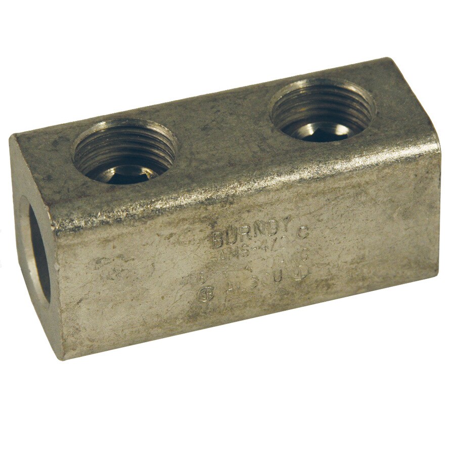
2. One suggestion i saw was finding 2 terminal ends with the same size circle for the 10 gauge and 4 gauge, then get a screw and nut (stainless steel?) and just tighten the two and then tape all around. Another idea was to use a split bolt. Do these ideas seem like a good idea? If so, would i add a fuse to the thinner wire side (10 gauge side) or the thicker side (4 gauge)?

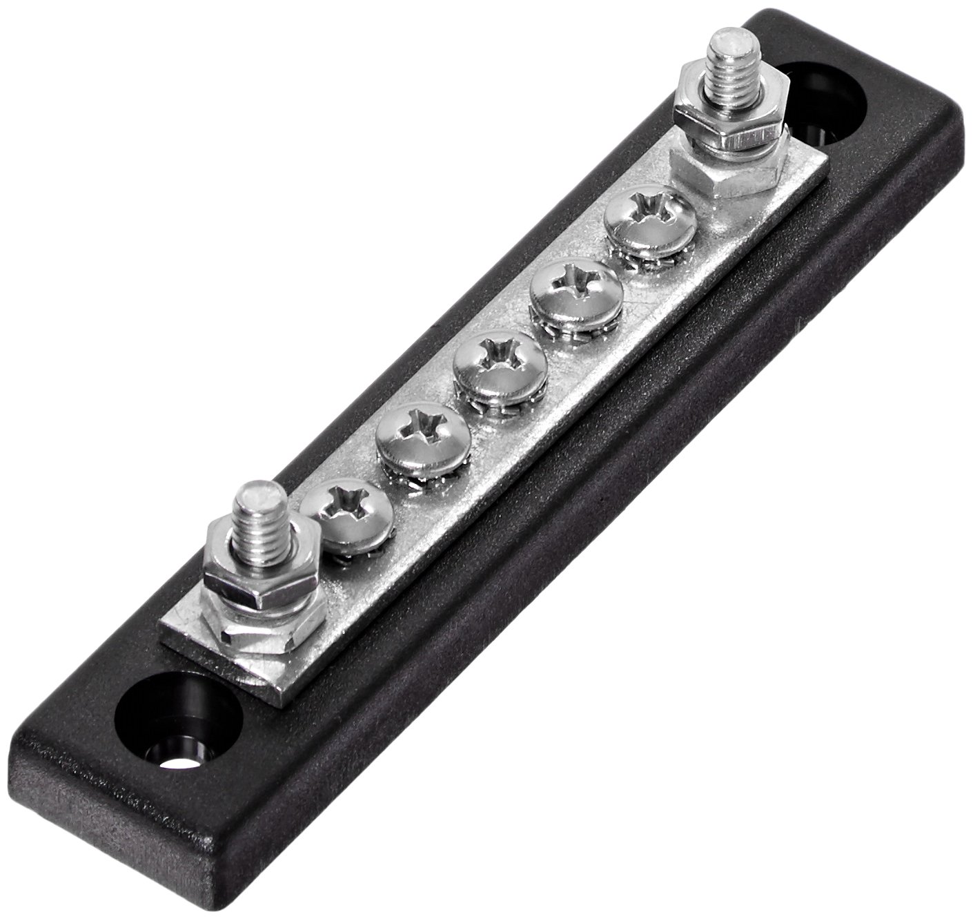
3. My system will be a 12 volt system with 2 batteries. I will have a 4 position selector switch so only one battery is in operation at all times and when it dies, i will just switch over to the new battery. I will have a bilge, aerator, depth finder, to add to my system (i eventually will add more). My loaded question is, where should i consider adding fuses and bus bars in my set up? It is difficult since many to most diagrams i see involve a starter battery and 12 different electronic devices and new words/devices that nobody knows, which make everything infinitely more convoluted for my pea brain.

Thanks for the help!

Troy
 
What I have done in the past is use a 4 gauge crimp connector and then strip like 2 inches of the 10 gauge and fold the bare conductor over on itself to
increase the diameter enough to make a secure crimp.
 
Another thing you can do is run the 4 gauge to a junction block/busbar mounted in the front of the boat and then run the 10 gauge to the motor from the busbar. With a busbar mounted in the front of the boat you will have the option to run other accessories in the future without rewiring the whole boat.
 
"Another thing you can do is run the 4 gauge to a junction block/busbar mounted in the front of the boat and then run the 10 gauge to the motor from the busbar. With a busbar mounted in the front of the boat you will have the option to run other accessories in the future without rewiring the whole boat."

I like this one the best.... richg99

p.s. Mostly, fuses should be placed nearest to the battery (or, in this case, the buss bar) rather than near the gauge/light/instrument etc.. The fuse protects the wire run, not the instrument.
 
Just replied and lost my reply...bummer. Thanks guys for the feedback. Makes me feel more confident about this whole process and i still have a LONG ways to go, but with every bit of feedback or article i read, i am slowly starting to get this process. You all are awesome. I am using the battery switch pictured and was wondering how i would wire the negative lines with the battery? I will have it rigged so each battery takes on all electronics at once and when it gets low, i will switch to the other battery. Most graphs include a starter engine connected to the battery, but i won't have a hp motor hooked up to the batteries. Any thoughts on the negative wiring? Thanks all.
 

Attachments

  • battery switch.png
    battery switch.png
    23.2 KB · Views: 3,615
Have a negative busbar in the front and one in the back. The only connection to the battery is to the switch and to the negative busbar closest to the battery.
 
timsmcm said:
Have a negative busbar in the front and one in the back. The only connection to the battery is to the switch and to the negative busbar closest to the battery.

Is it better to have a busbar in the back or just connect a wire from negative to negative on each battery? I won't be adding any motor in the future to this setup since it is a 14 footer.
 
I also recommend going with a bus bar. You should mount it somewhere out of the way, preferably in a compartment where it's not as exposed to elements, but can easily be serviced. Here's an example of a simple one. It should come with some sort of cover to keep it from shorting to ground, or other power circuits.

 
Here is another version. There are tons of different sizes and amperage ratings on Amazon.

richg99


https://smile.amazon.com/Sea-426710-1-Line-Buss-Terminal/dp/B002MBUBTA/ref=sr_1_1?ie=UTF8&qid=1489427074&sr=8-1&keywords=buss+bar+marine

71CCjsihzpL._SL1410_.jpg
 
An individual bus bar for each lead would be ideal in terms of easily replacing the TM receptacle in the future as well as adding accessories there. However, I wouldn't tie in any accessories that may get interference from the TM like a fish finder there. I would probably only use it as a connection point for navigation lights and maybe a 12V outlet or some other low amp draw lighting for the bow. If you only used it for say lighting and went with leds then you can probably just leave a single fuse near the battery. But if you anticipate too much more you can fuse the TM by itself at the bus bar on the 10 gauge and each individual attachment on their respective wires there too and then up the fuse near the battery accordingly.

I'm glad you posted this because I need to do the exact same thing and I plan to do it like I suggest above...which I only thought of thanks to your post and everyone else replies lol. I will tie in led nav lights and a 12V outlet (likely only for led UV lights and/or phone charger). And then can easily add some led courtesy lights or storage lights in the future.
 
I run a 6 gauge positive & negative from back to front with positive switched and fused no more than 18 inches from the battery. Each end of the boat has buss gangs for convenience. Both separate positive and negative.
 
Great replies all. Really helps me figure this stuff out. Love the variety of responses as well.
 
richg99 said:
"Another thing you can do is run the 4 gauge to a junction block/busbar mounted in the front of the boat and then run the 10 gauge to the motor from the busbar. With a busbar mounted in the front of the boat you will have the option to run other accessories in the future without rewiring the whole boat."

I like this one the best.... richg99

p.s. Mostly, fuses should be placed nearest to the battery (or, in this case, the buss bar) rather than near the gauge/light/instrument etc.. The fuse protects the wire run, not the instrument.

The fuse should always be placed as close to the battery as possible. No exception. I think ABYC says 7 inches but I would have to look it up. You can to to paneltronics website and download ABYC E-11. It gives all of the electrical requirements you will need.
 
https://lugsdirect.com/single-wire-lugs.htm
I use these to connect the wire to the buss bar or battery and they have a coupling with a allen set at each end to connect two different wire sizes. I then cover with a piece of heater hose and electrical tape it shut. Makes a full current connection for high loads like T/M
 
Believe it or not, Lowes often has a couple of different lugs that can be used.

Here is one that I've used before. richg99

https://www.lowes.com/pd/BURNDY-Aluminum-Lug/1000080309

050169989180.jpg
 
earl60446 said:
What I have done in the past is use a 4 gauge crimp connector and then strip like 2 inches of the 10 gauge and fold the bare conductor over on itself to
increase the diameter enough to make a secure crimp.

This
 
Top